
Railhead Damage
Introduction
I have worked on railhead damage of various types for almost my entire working life. During that time, my main areas of interest have been in rail corrugation (for which RailMeasurement provide measuring equipment, as shown elsewhere on this website), rolling contact fatigue (RCF) and a defect that my colleagues and I have christened a “stud”. I have been lucky in working extensively in academia, as a consultant and in the railway industry, most pertinently for a company that supplies rail grinding trains. During my career I have stood on the shoulders of giants not only in rail damage, but also in vehicle dynamics, acoustics and other areas.
This section of the website provides an essentially personal overview of railhead damage. This contribution is intended to complement rather than replace well-established references on rail defects1, 2, 3. It would be presumptuous to propose otherwise.
There are many similarities in the types of damage that occur on rails and wheels. For example, wheelburns and wheelflats are a consequence primarily of concentrated thermal input to rails and wheels from traction and braking effects respectively. Although we are aware of these similarities, we do not draw attention to them here.
Acknowledgements
I am grateful to several people for permission to use photographs. These include David Fletcher of Sheffield University, René Heyder of DB, Maurice Verheijen of Schweerbau GmbH, Brian Whitney of Network Rail and Charles Frederick, formerly of BR Research, to whom I am particularly grateful.
This contribution was initially drafted as a booklet for publication by a major supplier of railway equipment. This web-based presentation is intended to complement and be more widely accessible than that hard-copy publication. It can also be more readily updated.
Dr Stuart L Grassie
Stuart Grassie Engineering Ltd, March 2018
stuart@stuartgrassie.com
1 Atlas of wheel and rail defects
UIC, Paris, April 2004 (ISBN 2-7461-0818-6)
2 An international cross reference of rail defects 2nd edition, Cannon DF
UIC, Paris, June 2003 (ISBN 2-7461-0688-4)
3 Rail Defects Handbook: Some Rail Defects, their Characteristics, Causes and Control
RC 2400, Issue A, Revision 0, March 2006, Australian Rail Track Corporation Ltd.
Terminology
Rails are installed at a nominal angle of inclination, which is commonly in the range 1.43°-2.86° (1:40 to 1:20). This is usually equal to the angle of the wheel tread at the tread datum position so that a wheelset could ideally run with the datum position on each tread contacting the centre of each rail crown. Rails in switches and crossings and grooved rails for tram and light rail vehicles are often laid vertically.
Gauge is the distance between the two running rails. This is measured between the “gauge point” on the rails, which is at a distance of typically 12-14mm (depending on the network) below the reference line that is formed by a straight edge lying on the crown of both running rails in track.
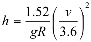
The high rail is the outer rail in a curve and the low rail is the inner rail. The difference in height is the cant, which compensates partially for curving forces. The equilibrium cant required for a vehicle on standard gauge track (distance of 1.52m between rail centres) to travel through a curve of radius R (m) at speed v (km/h) is
Cant excess or deficiency significantly influences curving behaviour of a vehicle, forces exerted on the rail and therefore rail damage. If the cant is less than the equilibrium value, vehicles curve with cant deficiency. If the cant is greater than this value vehicles curve with cant excess.

The area of the railhead on which wheels can run is considered to comprise several smaller areas, shown above, within which different types of damage can occur. The crown is essentially the area shown as A, while the shoulders (gauge towards the opposite rail, field facing the outside of the track) lie between A and B. The corners lie between B and C. The side of the rail is known as the face. Common rail sections (for example those defined in European and other standards) comprise a series of arcs, with a relatively large radius for the crown, a smaller radius for the shoulders and an even smaller radius for the corners. The European 60E1 profile comprises arcs of 300mm, 80mm and 13mm radius, while the 60E2 profile has arcs of 200mm, 70mm and 16mm.
In straight track, wheels should ideally run along the rail crown. Contact between wheels and the gauge face should occur only in severe curves. Contact occurs on the gauge shoulder in most curves, since this gives rise to a rolling radius difference between wheels on the same wheelset, thereby helping it to roll around the curve.

Damage categories
The term damage is used here to describe a change either in the structure of a rail or of the transverse or longitudinal profile that reduces rail life. The changes of greatest interest here occur at or very close to the point of contact between wheel and rail.
A primary distinction is made here between:
- damage that is continuous or quasi-continuous,
- damage that is periodic or quasi-periodic, or
- isolated damage.
Periodic damage with a wavelength of greater than about 10m (waves) is usually a result of vehicle dynamic behaviour. Damage with a wavelength of less than 3m is usually a form of corrugation.
Three broad and fundamental categories of damage are considered here:
- wear
- mechanical deformation
- thermal damage
These are not exclusive: there can be overlap between damage mechanisms and more than one damage mechanism may operate at a particular point on the rail.
Wear usually occurs relatively slowly; mechanical deformation more quickly (although still requiring many cycles of loading), whereas thermal damage typically occurs from a single cycle of loading.
The term spalling is used here to refer simply to detachment of a small particle of material from the rail surface by any cause.
Effects of maintenance are also considered separately to include changes to the running surface of the rail that arise from maintenance of the rail itself.
1. Fundamental damage mechanisms
1.1 Wear and plastic flow
Wear occurs whenever a wheel rolls over a rail and transmits a tangential force. Wear rates are low unless sliding between wheel and rail and/or tangential forces are consistently high. In practice the highest wear rates occur where slip is greatest, in particular when the wheel flange contacts the gauge face. In straight track a rail crown wear rate of 0.05-0.1mm per 10MGT of traffic would not be unusual, whereas wear rates in curves could be an order of magnitude greater than this and gauge face wear rates higher again (in the absence of lubrication).
Plastic flow is bodily deformation, without loss of material, that results from high loading normal and tangential to the wheel/rail contact. Both wear and plastic flow change the shape of a rail.
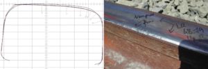
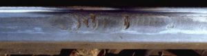
In straight track the crown of the rail wears to become slightly “flat”, conforming to the shape of the wheels that run over it. Some plastic flow occurs towards the gauge and field corners. The measurement shows a rail that has rolled a little to field, so contact is not along the centre of the rail crown and there is more wear of the gauge shoulder.
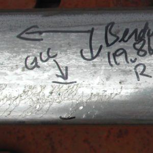
The photograph shows a case of abnormally rapid wear and plastic flow. This occurred in only a few days because the rail was transposed i.e. turned, so that the field side of the rail became the gauge. Contact stresses on the gauge corner were extremely high and flow occurred quickly to change the rail shape and reduce stresses to those that could be carried.
In curves that are sufficiently severe for there to be flange contact, the high rail usually wears until it conforms almost exactly to the corresponding flange root area on the wheel. Wear of the gauge face is known as side cutting.
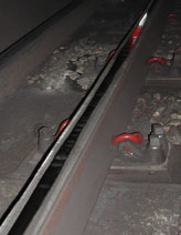
If friction is sufficiently high, the tangential force can pull material down the gauge face of the high rail, causing a lip of plastically flowed material that is detached by wheels. These slivers of material can then be seen lying alongside the rail.
Wear and deformation are best controlled with adequate lubrication, which can be applied to either the rail or the wheel.
The low rail tends to be flattened as a result of wear and plastic flow. Gauge and field corners can be quite abrupt as a result of the flowed material.
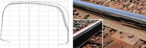
In extreme cases, plastic flow gives rise to flaking of the low rail with clear signs of detached material. This usually occurs only where friction is consistently high e.g. in tunnels and very dry, unlubricated areas. The loss of plastically flowed material (as in the photo) would be reflected in a high wear rate. The measurement of a low rail shows an early stage of the condition known as collapsed head. This occurs more readily in curves because tangential loads are higher.
1.2 Rolling contact fatigue / gauge corner cracking
“Fatigue” describes damage that occurs as a result of the incremental growth of a crack or series of cracks. ”Rolling contact fatigue” (RCF) describes the process in which cracks grow as a result of the contact stresses between a rolling wheel and the rail. Both normal and tangential stresses are required in order for RCF to develop.
RCF that is continuous or quasi-continuous is often found along the gauge corner or gauge shoulder of the high rail. This type of RCF is known as “head checking” or “gauge corner cracking” (GCC).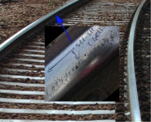
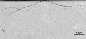
GCC is initiated by high tangential forces required for curving. The angle of the crack mouth on the rail indicates the angle of the force that initiated the crack: in the photograph above, the train would be moving towards the viewer. The force on the high rail would be backwards and towards the inside of the curve. Cracks start at the rail surface and develop into the rail at an angle of about 20° to the running surface. Typically there are many closely-spaced cracks, only a few millimetres apart along the rail as shown below.
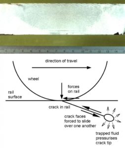
Development of GCC beyond the first few millimetres into the rail requires the presence of a liquid, in particular water. If the crack is oriented so that water can be trapped within it, this gives extremely high pressures and stress at the tip of the crack (a mechanism known as “hydraulic entrapment”). This mechanism drives the crack down through the layer of compressive residual stress near the running surface. At the edge of this layer, the crack tends to turn. If it turns down into the rail, it develops subsequently under bending and other bulk stresses. Such cracks can break a rail. Since there are usually many cracks at a similar stage of development, there may be multiple breaks. There is a great danger of derailment in such circumstances.
If the crack “turns” along the rail, it joins up with other cracks and a small piece of metal falls out. This is known as spalling.
If fluid is not present or if the crack is oriented so that water is expelled from it, GCC does not develop beyond the first few millimetres into a rail. This is the case in dry tunnels, where GCC may look severe, but is only superficial.
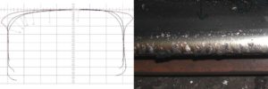
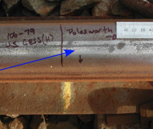
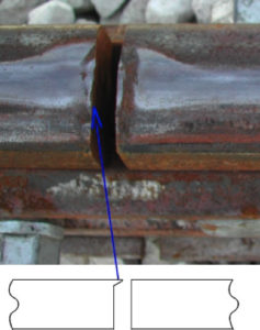
GCC initiates only occasionally on the low rail because tangential loads are usually low; and contact stresses are also lower because of the more conformal contact conditions. An example is shown of GCC on the low rail that has developed because of incomplete reprofiling around a weld in an area where trains are under high traction.
Quasi-continuous RCF occasionally occurs in straight track. If so, it is often the result of high locomotive traction, poor transverse profile or tight gauge, which forces the wheels to run along the gauge corner giving high contact stresses. RCF may occur on one rail if there is cant in straight track, since bogies then steer towards one rail.
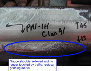
A successful and widely accepted treatment of quasi-continuous RCF is routinely to reprofile rails to establish a transverse profile that unloads critical areas of the rail (in particular the gauge shoulder) and also removes short cracks before they propagate into the rail. It is not necessary to remove cracks if the rail is profiled in such a way that cracks are no longer touched, since hydraulic entrapment can no longer operate to propagate the cracks.
RCF develops less quickly in harder rails provided these are profiled satisfactorily and this profile is maintained. There is also less plastic flow and wear on hard rails, so the profile changes more slowly than on a softer rail, and less maintenance is required in the long term. If the profile is inappropriate, RCF can develop more quickly because of the sustained high contact stresses.
1.3 Thermal damage
Although there is always some heat dissipated at the wheel/rail contact, this is rarely sufficient to cause a change in the microstructure or internal stresses in a rail. Such changes do, however, occur when wheels slip sufficiently.
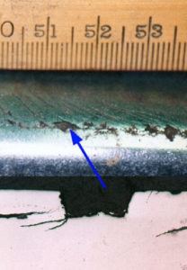
On rails that have been in service for a sufficiently long time, there is often one band or more of so-called “white phase” or “white etching layer” (WEL). These bands of WEL are extremely shallow (about 0.050mm deep) and comprise martensitic material that has resulted from many small wheelslip events, each of which is sufficient to heat the rail locally to the austenitizing temperature. The rapid quenching that arises from the rail’s high thermal inertia causes the transformation to martensite.
There are many cracks in the layer of WEL itself, but these cause the layer to detach; they do not propagate into the rail. The detached particles of WEL are essentially wear debris.
There is evidence that WEL has become less common with AC traction, probably as a result of better intrinsic wheelslip control.
2. Periodic damage associated with vehicle dynamics
2. Introduction
Periodic or quasi-periodic variations sometimes exist on rails with a wavelength of about 10-30m. Where this occurs, it is almost always the result of vehicle dynamic behaviour. Wear, plastic flow and rolling contact fatigue are often all periodic.
2.1 Straight track
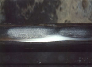
The most common periodic or quasi-periodic rail damage in straight track is a result of vehicle “hunting”. When this occurs, wheelsets and the vehicle oscillate from side-to-side in a very periodic manner. Where there is flange contact the rail appears almost identical to a high rail, with gauge face wear and RCF on the gauge corner. The opposite rail appears like a low rail, with a flattened profile. Half a cycle further along (5-15m typically), the rail that appeared like a high rail appears like a low rail, and vice versa.
There are several reasons that “hunting” appears in localised areas. The most common reasons are tight gauge and profiles that have worn to conform too closely to the wheels. These increase the “effective conicity” and reduce the vehicles’ “critical speed”. Trains hunted on the rails shown in Section 1.1 immediately after these were transposed because of the increase in conicity from running in the root of the wheel flange.
When a periodic pattern of such long wavelength becomes established in the rail, it is impossible to remove with current rail reprofiling techniques. Reprofiling can, however, be undertaken to reduce conicity, eliminate hunting and allow trains to run on the periodically worn rail.
Hunting is potentially a dangerous condition: apart from damaging rails, it can move the whole track laterally.

2.2 Curved track
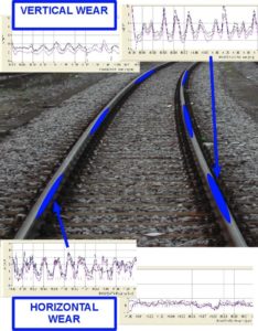
Periodic damage can occur in curved track, where it is superposed on the damage that would usually be seen in a curve. The most obvious result is periodically high gauge face wear and GCC on the high rail, and plastic flow on the low rail, which appears as a periodic vertical irregularity. This is illustrated by the measurements below.
Damage of this severity is rare and usually results from excitation of a lateral resonance of the vehicle. This dynamic behaviour is usually “triggered” by variations in lateral track geometry e.g. poorly finished welds or joints. Sometimes a feature as simple as a walkway across the track or a level crossing is a sufficient “trigger”.
GCC sometimes appears periodically in so-called “clusters” as a result of a similar mechanism. “Clusters” of GCC are a feature primarily of large radius curves, but occur also in straights. In tighter curves GCC is usually either continuous or absent.
The best way to avoid periodic damage of this type is to maintain good lateral geometry, thereby eliminating the “triggers” for dynamic excitation. Because vehicles respond differently to lateral irregularities, problems may exist on one railway with one set of rolling stock that does not exist on an almost identical railway with different rolling stock.
3. Corrugation and related damage
3. Introduction
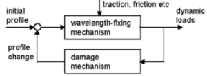
The most common form of periodic damage on rails is corrugation. A well accepted mechanism for corrugation formation is shown.
The “wavelength-fixing mechanism” (WFM) is the dynamic behaviour that “fixes” both the wavelength and the position of corrugation along the track.
All types of corrugation whose cause has been identified to date are “constant frequency” phenomena, whose wavelength is:
λ = v/f
v= predominant train speed, f = frequency of the WFM
WFMs that have been identified to date lie in the range of about 50-1200Hz. Examples of corrugation that occur from the following WFMs are considered here, in order of approximately increasing frequency:
| Type of corrugation (WFM) | Approximate frequency (Hz) |
| P2 resonance | 50-100Hz |
| Rutting | 50-150Hz |
| Trackform-specific | 300-500Hz |
| Pinned-pinned resonance | 450-1200 Hz |
The “damage mechanism” causes the dynamic load (vertical or tangential) to result in an irregularity. The most common damage mechanism is wear.A basic classification of corrugation is given here by considering different WFMs.
Because irregularities on a rail excite the dynamic behaviour, all corrugation can be reduced to some extent by ensuring a good longitudinal profile i.e. a “smooth” rail. Practical limits on irregularities left by typical reprofiling operations are proposed in a European standard1.
1Railway applications – track – Acceptance of work – Part 3, Acceptance of rail grinding, milling and planing work in track, European Standard, EN 13231-3, European Committee for Standardisation, rue de Stassart 36, B-1050 Brussels, May 2006
3.1 „P2 resonance“ corrugation
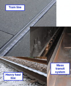
The so-called “P2 resonance” of the vehicle’s unsprung mass bouncing on the track stiffness is a common wavelength-fixing mechanism on all types of track, from trams to heavy haul railways. The examples shown are for a tram track in the street, a mass transit system, a freight railway, and a mixed passenger and freight line. Wear is the “damage mechanism” for the first two of these and plastic deformation for the others.
P2 resonance corrugation is a problem for metros in particular because it gives rise to low frequency “rumble” that is transmitted well into buildings. For conventional railways the wavelength of the resulting corrugation is usually at least several hundred millimetres, making the corrugation difficult to see.
 Low rail corrugation on the mixed passenger and freight line shown has occurred because the line is canted to suit passenger trains, and over-canted for the very much slower freight trains. Bogies steer badly in these conditions, giving very high tangential loading on the low rail. This causes quasi-continuous plastic flow, on which corrugation is superposed.
P2 resonance corrugation on non-ballasted track can usually be avoided using a sufficiently resilient, well-designed trackform.
A proven treatment of corrugation is to use harder rails as these reduce damage by both plastic flow and wear. Reprofiling should be undertaken routinely to retain an appropriate transverse profile that does not cause high stresses and RCF damage, and to minimise irregularities that “trigger” dynamic behaviour.
An occasional damage mechanism is yield of the rail in flexure. When this is the case the corrugation can be avoided using rail with higher flexural rigidity and strength. Dynamic loads are usually critical, so irregularities should be minimised.
3.2 Rutting
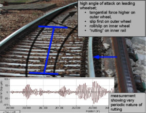
“Rutting” occurs mainly on the low rail in curves. It results from excitation of a flexural resonance of a wheelset, excited by high lateral tangential forces. Wear is very periodic and often occurs rapidly. Rutting is exacerbated by applied traction and by high angles of attack of bogies.
In existing track rutting can be reduced
- by reducing cant, thereby reducing the tangential force required for bogies to steer;
- by reprofiling to help steering;
- by controlling friction at the wheel/rail interface to reduce conditions for stick/slip.
Since rutting is a so-called “self-excited oscillation”, longitudinal irregularities are triggers but are not fundamentally important.
3.3 Trackform specific corrugation
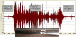
Some trackforms have pronounced resonances that act as unusual wavelength-fixing mechanisms. An example is shown of corrugation in the 30-100mm wavelength range that has occurred on the low rail in a curve. On one trackform, between about 8.88km and 9.09km, there is severe and very periodic corrugation whereas there is minimal corrugation on the other trackform.
3.4 Pinned-pinned resonance corrugation
“Pinned-pinned resonance” corrugation arises from excitation of a resonance of the rail in which it vibrates as a beam with nodes almost at the sleepers. Examples are shown of this type of corrugation on ballasted track and on a metro, where there is a mix of both pinned-pinned resonance and P2 resonance corrugation. This type of corrugation occurs primarily on straight track and on the high rail in curves. High dynamic loads result from the dynamically stiff support, so corrugation is often worse on the approach to sleepers than at the more flexible mid-span position, where dynamic loads are lower.
Pinned-pinned resonance corrugation is often associated with a loud “roaring” noise inside and outside the train (thereby giving rise to the term “roaring rails”).
The pinned-pinned resonance has the highest frequency of common wavelength-fixing mechanisms.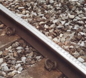
3.5 Belgrospis
‘Belgrospis’ are not corrugation, but clusters of cracks, which appear on the peak of pinned-pinned resonance corrugation (20-100mm wavelength), between the rail centre and the gauge corner. To date they have been recorded only on sections of the German high-speed network.
4. Discrete defects
4. Introduction
The most significant discrete defects are caused by rolling contact fatigue (RCF) and thermal effects.
4.1 Squats
Squats are RCF defects that occur in straight or gently curved track. They occur within the running band on the rail crown where the rail is heavily sheared from locomotive traction. Squats are sometimes known as “black spots”, where the dark area is a depression in the rail above the crack.
Squats are thought to initiate where small bits of hard material are trapped at the wheel/rail interface and cause one crack to grow rather than another. The direction of the crack can be felt, as with other types of RCF, by drawing a finger gently along the rail: the surface feels smooth when running a finger in the direction of traction but “ragged” in the opposite direction. The crack develops in the direction of the heavily sheared surface layer.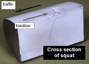
Essentially the same mechanism causes development of squats and GCC (Section 1.2). Transverse defects often result from squats that are left in track. Squats remain superficial in the absence of water.
4.2 Shells
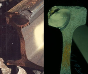
Shells are RCF defects that initiate several millimetres under the gauge corner of the high rail. A close relationship has been found between the defect rate from shells and a shell index (the so-called “Clayton number”):
![]()
A fatigue crack propagates initially parallel to the rail just under the gauge corner, then turns down into the rail to form a transverse defect (TD). The TD appears similar to that which occurs from a squat or from GCC.
The cleanliness of rail steel is now controlled deliberately to limit shells. Routine reprofiling is an important treatment for both squats and shells.
4.3 Wheelburns
Wheelburns occur where a wheelset has spun with little or no forward movement of the train. Concentrated heat input combined with rapid quenching from the body of the rail leads to localised thermal transformation. Transformation to martensite may occur, giving rise to brittle particles that are readily detached. Significant irregularities exist opposite one another on both rails. Thermal damage causes both surface and sub-surface cracking.
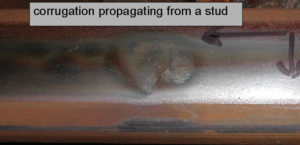
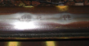
4.4 Studs
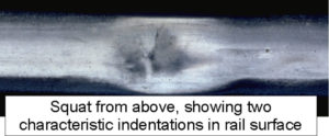
Studs appear superficially very similar to squats: in particular they have two characteristic indentations in the rail surface. Although their cause is not yet well understood, cross-sections and circumstantial evidence suggest that they may initiate from thermal damage. They are associated mainly with areas of high traction demand and where friction differs on the two rails e.g. in curves rather than straight track. They do not occur in areas of sustained high friction, particularly in dry tunnels. Studs usually occur on only one rail, although they can appear, often with different severity, opposite one another (when it may be difficult to differentiate them from a wheelburn). Sometimes the stud initiates corrugation, as shown here. Multiple studs are common.
There is some association between studs and changes in rolling stock, particularly from DC to AC traction.
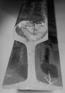
A cross section through a stud shows that there are sub-surface cracks, with a longer crack below the “running off” end of the crack mouth. These cracks cause the surface irregularities, with the larger irregularity above the longer crack. Although there are similarities with RCF, there are also significant differences.
Squats, shells, wheelburns and studs represent significant irregularities on the running surface of the rail, which result in high impact loading. They are also a source of transverse cracks, as a result of which ultrasonic inspection of the rail may be impossible. Consequently these defects should be removed, by localised grinding (which is possible only for the shallowest of defects), repair welding or rerailing. Routine grinding offers a viable preventative maintenance technique for most of these types of defects.
4.5 Isolated white etching layer (WEL)
Isolated patches of white phase or WEL can occur if wheelslip has been insufficient to cause a wheelburn or stud. These may appear opposite one another on both rails. At present it is not known if these are the origin of a more substantial defect, such as a stud, but they do represent a measurable irregularity.
Discontinuous patches of WEL are often the first sign of corrugation.
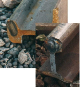
4.6 Plastic flow: rail end batter
In jointed track there is an irregularity as a result not only of the joint itself but also of the relatively low stiffness of the bolted joint. This irregularity gives rise to high dynamic loading. Material also flows more readily because of the poor constraint of each rail end by the adjoining rail. Rail end batter is the result of high loads and poor constraint.
This condition is best rectified by welding the rails to a satisfactory standard.
5. Spalling
5. Introduction
Spalling is regarded here as detachment of macroscopic particles from the rail surface for whatever reason. Spalls may be isolated or there may be several in the same area.
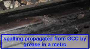
5.1 Spalling associated with RCF
When RCF is initiated at the rail surface e.g. GCC, cracks can develop several millimetres into the rail if a fluid such as water or a lubricant is present. When cracks reach a depth that is approximately that of the so-called “compressive residual stresses” (typically about 5mm), they tend to go in one direction or another i.e. they “branch”.
If a crack branches approximately parallel to the rail surface, it tends to meet up with another crack to form a spall. The crack is then no longer active and the spall is sometimes worn away by traffic.
The conditions in which a crack branches parallel to the rail surface and those in which it branches down into the rail (potentially to form a transverse defect) are not yet fully understood.
There is some evidence that grease exacerbates spalling.
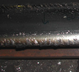
5.2 Spalling associated with plastic flow
Plastic flow results from high contact stress normal and tangential to the wheel/rail contact. In extreme cases flow gives rise to debris that spalls from the rail surface. This condition is often seen on the low rail of curves in dry underground tunnels, where friction is extremely high.
5.3 Spalling associated with thermal damage and wheelburns
The heat input to the rail from a spinning wheel usually gives rise to martensitic white phase (WEL) at the rail surface and also thermal cracking near the surface. Spalling occurs when the WEL becomes detached or the thermal cracks coalesce.
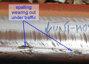
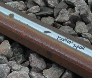
5.4 Ballast spalls
Ballast spalls occur when particles of ballast become trapped between wheel and rail. Usually these defects are relatively benign and wear out, but in some circumstances they can initiate squats or corrugation. Some damage of this type can be avoided by ensuring that ballast is brushed from the rails after reballasting of track, but ballast can sometimes be picked up by the slipstream of the train. A small ballast spall is apparent in the photograph in Section 1.3.
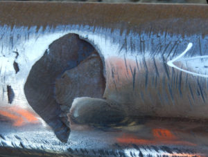
5.5 Spalls associated with studs
If studs (Section 4.4) are allowed to develop, they tend to spall out as shown. The stud has initiated towards the field side of the rail (towards the bottom of the photograph), grown into the rail and then propagated transversely. These cracks appear to develop by a mechanism of conventional fatigue (as evidenced by the “beach marks” on the fracture surface) under the surface layer of compressive residual stress, then rise up to the rail surface beyond this layer. Quite a large portion of the rail surface can then spall out, as shown here.
Because studs develop transversely, they differ significantly from GCC (Section 1.2), squats (Section 4.1) and shells (Section 4.2). Those defects develop substantially longitudinally.
6. Effects of maintenance
6. Introduction
Routine maintenance of rails is desirable and in many cases an essential part of limiting the development of significant rail defects. The principal components of rail maintenance are lubrication, which greatly reduces wear, and reprofiling. Reprofiling, which is most commonly undertaken by grinding, is essential to remove existing corrugation. It is also an essential component of current treatments of RCF. Asymmetric reprofiling helps vehicles steer through curves, thereby reducing all types of defects that occur in curves, while establishment of a more appropriate profile in straight track can reduce hunting.
Hard rails offer a potential treatment for most rail defects, except thermal damage. However, hard rails should only be used if the profile is both appropriate and also routinely maintained: soft rails are more “forgiving” than hard rails.
Maintenance activities occasionally leave features that are both undesirable and avoidable. It is important to recognise features that are inevitable and those that can be avoided.
6.1 Rail grinding issues
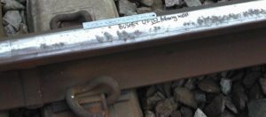
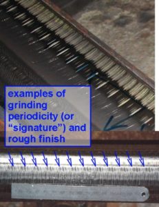
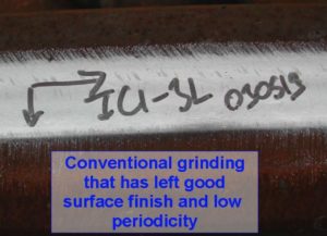
Conventional rail grinding is undertaken with motors that rotate about an axis normal to the rail, typically at 50Hz. For a typical grinding speed of 5-8km/h, this gives a periodic grinding signature at 25-40mm wavelength. Severe grinding, large stone grits and grinding “chatter” can give a pronounced signature, such as that shown. Traffic may cause a characteristic “whistle” until scratches wear away.
Coincidence of the grinding signature with corrugation wavelengths should be avoided as corrugation otherwise returns quickly.
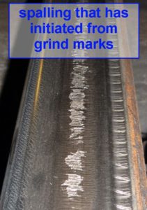
Extreme cases of deep residual grinding scratches, hard rail and low contact stress can initiate surface spalling. This is undesirable and avoidable.
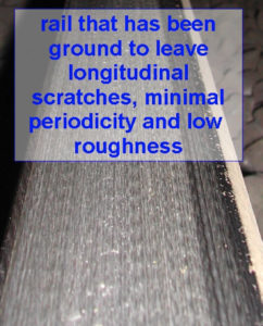
Other grinding techniques can give lower longitudinal roughness but are less able to modify the rail’s transverse profile.
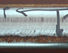
6.2 Rail planing issues
Rails are planed in order to remove a significant depth of damaged material (typically >1mm) or deliberately to change the rail’s transverse profile. Discontinuities in profile that give rise to high contact stresses can be created more easily than with grinding, because of the greater depth of metal removal. This is the case here, where a central plateau with abrupt edges has resulted from planing. The characteristic coils of swarf that result from this operation sometimes lie alongside the rail.
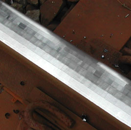
6.3 Rail milling issues
When a rail is milled, the milling cutters have been pre-set to establish a specified transverse profile. It is therefore both more difficult than with other reprofiling techniques to vary the profile and also more difficult to establish an “incorrect” profile, unless the specified profile is itself incorrect.
Individual milling cutters create a characteristic finish of small, uniform irregularities which wear out under traffic. In extremely noise-sensitive locations these are sometimes removed with longitudinal “shuffle-block” grinding. Small chips of swarf result from milling.
6.4 Friction enhancement
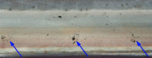
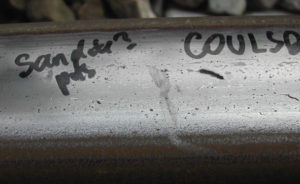
Sand is often injected into the wheel/rail contact to reduce wheelslip. During autumn in temperate countries (the “leaf fall” season) a fluid containing abrasive particles is sometimes used to enhance adhesion. Sand or other abrasive particles cause small pits. These pits are a common feature of tram systems, where sand is widely used.
7. Feedback guidelines
When you are recording a rail defect, I would suggest that you note the following information. If your railway system has a problem with a particular defect, I would be happy to consider undertaking an investigation as a consultancy project but I cannot offer to comment otherwise.
Desirable information
- type of traffic:
- high speed,
- passenger/freight
- dedicated freight line
- heavy haul
- metro (surface or underground?)
- tram / light rail
- speed of traffic at site
- are vehicles under traction or braking?
- Is the rail in straight track or is it the high or low rail in a curve?
- if in curve, what is the approximate radius and cant; is there lubrication?
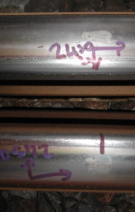
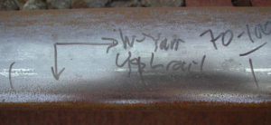
- A photograph on which you have drawn one arrow pointing in the direction of traffic and another towards the gauge face of the rail. Please also point to any unusual features that you consider significant.
NB There are several examples in this booklet of photographs such as this e.g. in Sections 1.2, 4.5, 6.1 and 6.2. If you don’t have a pen to mark the rail, please send the photo with some annotation to show the defect of interest.
Notes to help with taking a good photograph
- Although black ink is used in most of the photos shown here, pink shows up very well in photos.
- Take the photograph from about 0.5-1m distance, and if using a flash e.g. at night or in a tunnel, ensure that the camera is pointed so that the flash reflects away from the rail rather than into the lens.
- Automatic cameras often focus better in the dark if someone shines a torch on the rail that you want to photograph.
Supplementary information e.g.
- rail type (look at rolling mark on web of rail), rolling date and (if possible) date of installation
- milepost
- profile (“design” and measurement of actual profile)
- date last ground
- other feature(s) that you consider important.
8. Causes of surface damage of rails
8 Introduction
With the principal exception of thermal damage, most forms of surface damage of rails are caused by normal and tangential stresses at the wheel/rail contact. These stresses result from loading on the rails, which in turn result from the way that a vehicle behaves on the track. Most damage is worse in curves, where tangential loads tend to be higher than in straight track, because these are required in order to steer the bogie (and vehicle) through the curve. Different types of damage tend to occur on high and low rails because of both the different forces acting on them and the different contact conditions. To give a holistic understanding of some fundamental reasons for surface damage and why particular treatments work, this section contains the following:
- Calculations of the tangential forces resulting from a combination of curving and applied traction.
- A description of so-called “shakedown”, which provides a relatively simple method of determining whether a wheel or rail can carry applied loads.
8.1 Wheel/rail contact forces: effects of curving and applied traction
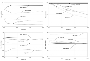
The greatest influences on tangential force are curve radius, applied traction, bogie design and applied cant. The effects of curve radius and applied traction on the magnitude and direction of tangential force are illustrated below for a vehicle with fairly conventional suspension. The magnitude of tangential force is shown as the so-called “traction ratio” i.e. the ratio of tangential to normal force, which is limited by the coefficient of friction (assumed here to be 0.4).
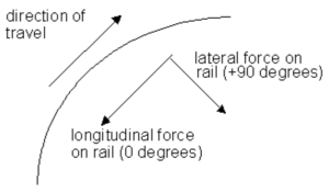
The direction of tangential force is shown by the so-called “phase”. A tangential force that pushes the rail “backwards” (and the train forwards) has a phase of 0°. A tangential force with a phase of +90° pushes a rail towards the inside of a curve.
Calculations are shown of the tangential force at the leading and trailing wheelsets of a bogie for wheels on the high and low rails in a curve and for two conditions of applied traction: a coasting vehicle (T/N=0), and a locomotive or power car (T/N=0.28). The vehicle is curving at equilibrium cant. The range of applied traction in practice is typically 0<= T/N <=0.42. The traction that a locomotive or power car can apply is limited by available power at higher speed, and at lower speeds by available adhesion.
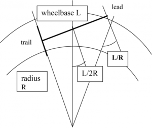
If a bogie were rigid, it would curve approximately as shown, with the trailing wheelset radial to the curve and almost at the so-called “equilibrium rolling line”, where the rolling radius difference between wheels compensates for the difference in radius between inner and outer rails. The leading wheelset has both an “angle of attack” to the direction of travel and curves outside the equilibrium rolling line. Consequently for almost all conditions, tangential forces are very much higher at the leading wheelset: leading wheels cause more damage. Decreasing curve radius in general increases tangential curving force.
A bogie “steers” better i.e. with lower tangential forces, if the in-plane suspension is made more flexible: this allows the leading wheelset to become more radial and move towards the equilibrium rolling line. Applied traction counteracts this effect, and straightens the bogie out i.e. makes it curve more like a rigid bogie. Under high applied traction, wheels on the high rail are close to slipping even in gentle curves.
Increasing cant tends to move the trailing wheelset towards the inner rail, thereby allowing the leading wheelset to develop even higher “angle of attack”, greater tangential force and a greater difference in tangential force across a wheelset. Excessive cant exacerbates surface damage.
Conversely, under cant deficiency the trailing wheelset moves out to the high rail and the leading wheelset adopts a lower angle of attack. Tangential forces are very much more favourable. If movement towards the high rail gives more gauge face contact, lubrication should be provided to reduce wear.
For the leading wheelset the high rail wheel pushes the rail backwards and towards the inside of a curve for the full range of applied traction; the phase varies relatively little. This is consistent, for example, with the small (but significant) variation in direction of GCC cracks seen on the high rail. The direction of tangential force on the low rail is determined primarily by the angle of attack, which forces the rails to the inside of the curve (lateral force, corresponding to a phase of +90°). This is consistent with most damage seen on the low rail, particularly plastic flow. A longitudinal braking force is superposed on this for low applied traction, and a driving force for applied traction of T/N=0.28. For intermediate values of T/N, which are typical of metro vehicles with all wheels motored, there is a purely lateral force on the low rail.
9. References
“Modelling of railway track and of vehicle/track interaction at high frequencies”
Vehicle System Dynamics, 1993, 22,209-262 (invited “state-of-the-art” paper, with K Knothe)
“Rail corrugation: characteristics, causes and treatments”
Journal of Rail and Rapid Transit, Procs of I mech E, 1993, 207F, 57-68 (with J Kalousek)
“Short wavelength rail corrugation: field trials and measuring equipment”
Wear, 1996, 191, 149-160
“Measurement of railhead profiles: a comparison of different techniques”
Wear, 1996, 191, 245-251
“Rolling contact fatigue of rails: characteristics, causes and treatments”
Procs of 6th Intnl Heavy Haul Railway Conference, Cape Town, 1997, pp381-404 (with J Kalousek)
“Requirements for transverse railhead profile and railhead roughness following grinding”
Procs of 6th Intnl Heavy Haul Railway Conference, Cape Town, 1997, pp549-564
“Corrugation on North American transit lines”
Vehicle System Dynamics Supplement, 1998, 28, 5-17 (with JA Elkins)
“Rail corrugation mitigation in transit”
Research Results Digest, Transit Cooperative Research Program, National Research Council, USA, number 26, June 1998 (with BJ Brickle, JA Elkins, SJ Handal)
“Measurement of longitudinal rail irregularities and criteria for acceptable grinding”
Journal of Sound and Vibration, 1999, 227, pp949-964 (with MJ Saxon and JD Smith)
“Alleviation of rolling contact fatigue by grinding the worn rail profile”
Procs of 7th Intnl Heavy Haul Railway Conference, Brisbane, 2001 (with P Nilsson)
“Rail defects – an overview”
Fatigue and Fracture of Engineering Materials and Structures, special issue on wheel / rail interface, 2003, 26, pp865-886 (invited paper, with D Cannon, K-O Edel and KJ Sawley)
“Rolling contact fatigue on the British railway system: treatment”
Wear, 2005, 258/7-8,1310-1318, (also Procs. Of 6th International conference on Contact Mechanics and Wear of Rail/Wheel Systems, A Ekberg, JW Rinsberg and R Lunden (eds))
“Tractive effort, curving and surface damage of rails, Part1: forces exerted on the rails”
Wear, 2005, 258/7-8, 1235-1244 (also Procs. Of 6th International conference on Contact Mechanics and Wear of Rail/Wheel Systems, A Ekberg, JW Rinsberg and R Lunden (eds)), (with JA Elkins)
“Traction and curving behaviour of a railway bogie”
Vehicle System Dynamics, 2006, volume 44 supplement, 883-891 (also Procs of the 19th IAVSD Symposium, Dynamics of vehicles on roads and tracks, Milan, September 2005), (with JA Elkins)
“Development of corrugation as a result of varying normal load”
Procs. Of 7th International conference on Contact Mechanics and Wear of Rail/Wheel Systems Brisbane, September 2006, Wear, 2008, 265/9-10, 1150-1155 (with JW Edwards)
“Rail corrugation: characteristics, causes and treatments”
Journal of Rail and Rapid Transit, Procs of I mech E, 2009, 223F, 581-596 (Review Paper, update of ref [33])
“’Squats’ and ‘Studs’ in Rails: Similarities and Differences”
IHHA conference, Calgary, June 2011 (with DI Fletcher, AE Gallardo-Hernandez and P Summers)
“Squats and squat-type defects in rails: the understanding to date”
Journal of Rail and Rapid Transit, Procs of I mech E, 2012, 226F, 235-242 (Review Paper)
“’Studs’: a squat-type defect in rails”, Journal of Rail and Rapid Transit
Procs of I mech E, 2012, 226F, 243-256 (with DI Fletcher, AE Gallardo-Hernandez and P Summers)
“Rail irregularities, corrugation and acoustic roughness: characteristics, significance and effects of reprofiling on different types of railway system”
Journal of Rail and Rapid Transit, Procs of I mech E, 2012, 226F, 542-557
“Traction, curving and surface damage of rails, Part 2: rail damage”
Procs of 9th Intnl Conference on Contact Mechanics and Wear of Rail/Wheel Systems, Chengdu, China, 27-30 August 2012, paper 1.1, pp1-8
”Measurement of long wave irregularities on rails”, in “Noise and vibration mitigation for rail transport systems”
JCO Nielsen et al (eds), Notes on Numerical Fluid Mechanics and Multidisciplinary Design, 2015, vol 126, pp643-649 (also Proceedings of 11th Intnl Workshop on Railway Noise, Uddevalla, Sweden, 9-13 September 2013)
“Traction, curving and surface damage of rails, Part 2: rail damage”
JRRT, Procs of ImechE, 2015, 229F, 330-339 (Published online before print, 11 July 2014, doi: 10.1177/0954409714541648)
“Studs and squats: the evolving story”
Procs of 11th International Heavy Haul Association conference, Perth, Australia, June 2015, pp1065-1070
“Studs and squats: the evolving story”
Wear, vol 366-367, pp194-199, 2016 (also Procs of 10th Intnl Conference on Contact Mechanics and Wear of Rail/Wheel Systems, Colorado Springs, USA, August 2015)
“Routine measurement of long wavelength irregularities from vehicle-based equipment”
In “Noise and vibration mitigation for rail transport systems”, David Anderson et al (eds), Notes on Numerical Fluid Mechanics and Multidisciplinary Design, 2018, vol 139, chapter 24 (also Proceedings of 12th Intnl Workshop on Railway Noise, Terrigal, NSW, Australia, 13-15 September 2016)